

Overview of Reinforced Concrete Design Standards
Table of Contents
What is BS 8110?
Reinforced Concrete Design is the British Standard that deals with the design, materials, and construction of buildings and structures in reinforced concrete, prestressed concrete, and precast concrete. It is written in limit state terms, meaning it evaluates structural performance against defined limiting conditions rather than using permissible stress methods.
The standard is organised into three parts:
-
Part 1: Code of practice for design and construction
-
Part 2: Design charts for singly reinforced beams, doubly reinforced beams, and rectangular columns
-
Part 3: Design charts for circular columns and other elements
BS 8110 introduced the concept of limit state design, applying partial safety factors to both material properties and loads. This represented a significant advance over earlier permissible stress approaches.
Eurocode 2: The Current European Standard
Eurocode 2 (BS EN 1992) applies to the design of buildings and other civil engineering works in plain, reinforced, and prestressed concrete. It is concerned with requirements for resistance, serviceability, durability, and fire resistance of concrete structures.
Eurocode 2 consists of four parts:
-
EN 1992-1-1: General rules and rules for buildings
-
EN 1992-1-2: Structural fire design
-
EN 1992-2: Concrete bridges
-
EN 1992-3: Liquid retaining and containment structures
The transition from BS 8110 to Eurocode 2 represents one of the most significant changes to concrete design practice in decades.
Key Differences Between BS 8110 and Eurocode 2
While both standards are based on limit state principles, several important differences exist:
| Aspect | BS 8110 | Eurocode 2 |
|---|---|---|
| Concrete strength notation | fcu (cube strength) | fck (cylinder strength) |
| Steel strength | 460 N/mm² or 500 N/mm² | 500 N/mm² (characteristic) |
| Shear enhancement | Increases resistance within 2d of support | Reduces design shear force by av/2d |
| Deflection rules | Span-to-depth ratios | Span-to-depth ratios (similar approach) |
| Punching shear | Less shear reinforcement required | More demanding requirements |
Research has shown that differences between ACI 318 and BS 8110 are minor for flexure, moderate for axial compression, and major for shear. Similar comparative studies exist between BS 8110 and Eurocode 2.
Key Principles of Reinforced Concrete Design
Limit State Design Philosophy
Limit state design recognises that a structure may become unsatisfactory in several ways, each of which must be considered independently against defined limits of satisfactory behaviour. The two primary limit states are:
-
Ultimate Limit State (ULS): Concerns structural safety — collapse, buckling, fatigue, and loss of equilibrium
-
Serviceability Limit State (SLS): Concerns deflection, cracking, and durability
In limit state analysis, partial safety factors are applied separately to both loads and material stresses. In ultimate limit state design, the characteristic strength of a material is modified by a partial safety factor to give the ultimate design strength.
Partial Safety Factors
BS 8110 specifies the following partial safety factors:
-
For concrete: γm = 1.5
-
For steel: γm = 1.15
-
For loads (dead): γf = 1.4
-
For loads (live): γf = 1.6
These factors account for variations in material properties and loading conditions.
Design for Flexure
Flexural design involves calculating the required area of tension reinforcement to resist applied bending moments. The key parameter is the K factor:
K=Mbd2fcuK=bd2fcuM
Where:
-
M = design moment
-
b = section width
-
d = effective depth
-
fcu = characteristic concrete cube strength
BS 8110 stipulates that if K ≤ 0.156, no compression steel is required (for singly reinforced sections). If K exceeds this value, compression reinforcement must be added.
Design for Shear
Shear design in BS 8110 involves checking the concrete shear stress and providing shear reinforcement (links/stirrups) where necessary. The standard enhances shear resistance within 2d of supports by applying a factor of 2d/av, where av is the clear shear span. This differs from Eurocode 2, which reduces the design shear force by av/2d.
Design for Deflection
BS 8110 uses deemed-to-satisfy span-to-depth ratio methods for ensuring compliance with deflection criteria. These rules provide economic solutions for the vast majority of designs. More rigorous checks involve calculating actual deflections using elastic analysis with cracked section properties.
Design for Cracking
Crack control is essential for durability and appearance. BS 8110 provides rules for minimum reinforcement and bar spacing to control crack widths. The serviceability limit state for cracking ensures that cracks do not compromise the structure’s durability or appearance.
Design of Specific Reinforced Concrete Elements
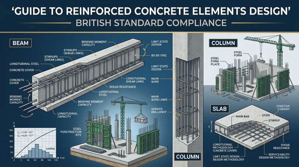
Beam Design to BS 8110
Reinforced concrete beam design is one of the most common tasks for structural engineers. The design process covers:
-
Singly reinforced beams: When the applied moment can be resisted by tension reinforcement alone
-
Doubly reinforced beams: When compression reinforcement is required due to high moments or depth restrictions
-
Continuous beams: Where moments are redistributed according to BS 8110 provisions
Fully worked examples covering singly and doubly reinforced beams, continuous beams, and cantilever beams are widely available.
Step-by-step beam design process:
-
Determine design loads and moments
-
Calculate the K factor using K = M / (bd²fcu)
-
If K ≤ 0.156, design as singly reinforced
-
If K > 0.156, design as doubly reinforced
-
Calculate lever arm (z) and area of tension steel (As)
-
Check shear and provide links
-
Check deflection and cracking
-
Detail reinforcement according to BS 8110 requirements
Column Design to BS 8110
Column design involves considering axial loads combined with uniaxial or biaxial bending. BS 8110 provides two formulas for the design of short braced columns in clauses 3.8.4.3 and 3.8.4.4.
The area of longitudinal steel for columns resisting axial loads and bending is normally calculated using the design charts in Part 3 of BS 8110. Design charts provide a visual method for selecting reinforcement ratios based on the ratios N/bh and M/bh².
Types of columns covered:
-
Short braced columns supporting axial loads
-
Columns with uniaxial bending
-
Columns with biaxial bending
-
Slender columns
Slab Design to BS 8110
Slab design covers one-way spanning solid slabs, two-way spanning solid slabs, and flat slabs. The design process involves calculating moments using coefficients from BS 8110, then designing reinforcement for flexure and shear.
BS 8110 provides moment and shear coefficients for the design of restrained slabs. These coefficients simplify the analysis of continuous slab systems.
Types of slabs covered:
-
One-way spanning solid slabs
-
Two-way spanning solid slabs
-
Flat slabs
-
Ribbed and waffle slabs
-
Post-tensioned slabs
Foundation Design to BS 8110
Foundation design includes pad footings, strip footings, raft foundations, and pile caps. The design must consider both structural requirements and geotechnical bearing capacity.
BS 8110 foundation design involves checking punching shear, bending moments, and reinforcement requirements. A study of a 33-storey reinforced concrete building using ProtaStructure in compliance with BS 8110 demonstrated the importance of proper foundation design for uniformly distributing heavy loads and minimising differential settlement.
Wall Design to BS 8110
Reinforced concrete walls may be designed as load-bearing or non-load-bearing elements. Design considerations include in-plane shear, out-of-plane bending, and slenderness effects.
Software Tools for Reinforced Concrete Design to British Standards
Several software platforms support reinforced concrete element design to BS 8110:
CYPECAD
CYPECAD is a powerful structural design and analysis tool that supports the design of reinforced concrete structural elements including columns, beams, slabs, and foundations. It allows non-linear analysis using the OpenSees analysis engine and includes BIM modelling capabilities.
Key features:
-
Design of columns, beams, slabs, and foundations
-
Punching shear checks
-
Seismic design of reinforced concrete nodes
-
Fire resistance checking
-
Import of IFC, DXF, and DWG files
-
Integration with CYPE 3D for steel structures
IDEA StatiCa
IDEA StatiCa offers solutions for the structural design of concrete elements such as beams, walls, and columns, as well as special solutions for discontinuity regions and anchoring. IDEA StatiCa Beam is a dedicated program for the analysis and design of concrete beams.
Key features:
-
Realistic reinforcement layouts
-
3D anchoring into reinforced concrete block design
-
Non-linear analysis
-
Code-compliant verification
-
Customised reports with PDF and Word export
ProtaStructure
ProtaStructure is an integrated structural engineering software that combines modelling, analysis, and detailing in one platform. It supports projects involving concrete, steel, and composite structures and includes support for British Standards (BS 8110, BS 5950, BS 6399).
ADC (Oasys Software)
ADC is a structural design software for analysing and designing reinforced concrete beams, slabs, columns, and piles. It supports BS8110-1, Eurocode 2, ACI 318, and other global design codes.
PROKON
PROKON 5.3 Concrete provides automatic rebar detailing for all reinforced concrete elements and supports BS8110 (1985 and 1997) among other design codes.
Practical Design Workflow
Step 1: Define the Structural System
Begin by establishing the structural layout, including beam and column positions, slab spans, and load paths. Consider architectural constraints and serviceability requirements.
Step 2: Determine Design Loads
Calculate dead loads (self-weight, finishes, services) and live loads according to BS 6399 or relevant loading standards. Apply appropriate load factors for ultimate and serviceability limit states.
Step 3: Analyse the Structure
Perform structural analysis to determine bending moments, shear forces, and axial loads. Use appropriate analysis methods — from simple coefficient methods for continuous beams to computer-based frame analysis for complex structures.
Step 4: Design Individual Elements
Design each reinforced concrete element (beam, column, slab, foundation) according to BS 8110 requirements. Calculate required reinforcement areas and check all limit states.
Step 5: Detail Reinforcement
Prepare reinforcement drawings showing bar sizes, spacing, curtailment, and anchorage details. Ensure compliance with BS 8110 detailing rules for cover, spacing, and lap lengths.
Step 6: Verify and Document
Check all calculations and produce a design report with references to the relevant BS 8110 clauses. Include reinforcement schedules and bar bending schedules.
Advantages and Limitations of BS 8110
Advantages
-
Well-established: Decades of use have refined the standard and its application
-
Design charts: Part 3 provides convenient design charts for common elements
-
Simplicity: Some provisions are simpler than Eurocode 2 equivalents
-
Familiarity: Many practicing engineers are experienced with BS 8110
-
Existing structures: Essential for assessing and modifying existing buildings
Limitations
-
Superseded: Eurocode 2 is now the primary standard for new design in the UK
-
Shear provisions: BS 8110 allows less shear reinforcement than EC2, which may not reflect modern understanding
-
Punching shear: BS 8110 requires less shear reinforcement than EC2 and MC2010
-
Material strengths: Limited to lower concrete strengths compared to modern practice
-
Seismic design: Less comprehensive seismic provisions than Eurocode 8
Transition from BS 8110 to Eurocode 2
The transition from BS 8110 to Eurocode 2 represents a significant change in concrete design practice. Key differences to understand include:
-
Concrete strength: BS 8110 uses cube strength (fcu) while EC2 uses cylinder strength (fck)
-
Shear design: Different approaches to shear enhancement near supports
-
Punching shear: More demanding requirements in EC2
-
Deflection: Similar span-to-depth approaches but with different coefficients
-
Detailing: Different rules for cover, spacing, and anchorage
Engineers transitioning from BS 8110 to Eurocode 2 should study the key differences carefully and use appropriate software tools that support both codes during the transition period.
Frequently Asked Questions
What is BS 8110?
BS 8110 is the British Standard for the structural use of concrete. It provides recommendations for the design, materials, and construction of buildings and structures in reinforced concrete, prestressed concrete, and precast concrete. It is written in limit state terms and was the primary UK concrete design code before Eurocode 2.
Is BS 8110 still valid?
BS 8110 has been superseded by Eurocode 2 (BS EN 1992) for new design work in the UK. However, it remains valid for assessing existing structures designed to BS 8110 and for remedial works. Understanding BS 8110 is essential for engineers working with the existing building stock.
What is the difference between BS 8110 and Eurocode 2?
Key differences include the notation for concrete strength (fcu vs fck), shear design approaches, punching shear requirements, and detailing rules. Eurocode 2 generally requires more shear reinforcement and has more demanding punching shear provisions than BS 8110.
What software supports BS 8110 design?
Several software packages support BS 8110 design, including CYPECAD, IDEA StatiCa, ProtaStructure, ADC (Oasys), and PROKON. These tools can analyse and design reinforced concrete beams, columns, slabs, and foundations according to BS 8110 requirements.
How do I design a reinforced concrete beam to BS 8110?
Beam design involves calculating design moments, determining the K factor (K = M / bd²fcu), designing for flexure (tension and compression reinforcement as needed), checking shear and providing links, and verifying deflection and cracking. Design charts in BS 8110 Part 3 provide convenient aids for reinforcement selection.
What are the partial safety factors in BS 8110?
BS 8110 specifies partial safety factors for materials (γm = 1.5 for concrete, γm = 1.15 for steel) and loads (γf = 1.4 for dead loads, γf = 1.6 for live loads). These factors account for variations in material properties and loading conditions.
What is limit state design?
Limit state design is a philosophy that evaluates structural performance against defined limiting conditions. It considers both ultimate limit states (safety) and serviceability limit states (deflection, cracking). Partial safety factors are applied to both loads and material strengths to ensure adequate reliability.
Can I use BS 8110 for seismic design?
BS 8110 provides limited seismic provisions. For structures in seismic regions, Eurocode 8 (BS EN 1998) should be used in conjunction with Eurocode 2. BS 8110 was not developed with modern seismic design principles in mind.
Final Thoughts
Reinforced concrete elements design to British Standard remains a vital skill for structural engineers. While Eurocode 2 has become the standard for new design, BS 8110 continues to be essential for assessing and modifying the vast stock of existing buildings designed to British Standards.
The key principles of limit state design, partial safety factors, and the design of beams, columns, slabs, and foundations form the foundation of reinforced concrete design practice. Software tools like CYPECAD, IDEA StatiCa, and ProtaStructure provide powerful support for these design tasks, enabling engineers to work efficiently and accurately.
For engineers transitioning from BS 8110 to Eurocode 2, understanding the key differences in shear design, punching shear, and material strength notation is crucial. Both standards represent significant achievements in structural engineering, and proficiency in both is valuable for any practising engineer working with reinforced concrete.
Our Paid Service
“We do not sell or provide any software. We only offer professional support services. If any software on your system is not working properly, or you are facing installation errors, crashes, or any other technical issue — just contact us. We will help you fix the problem quickly and remotely via AnyDesk. No software will be provided from our side — only expert troubleshooting and support.”