

Overview of NI Circuit Design Suite 14.3
Table of Contents
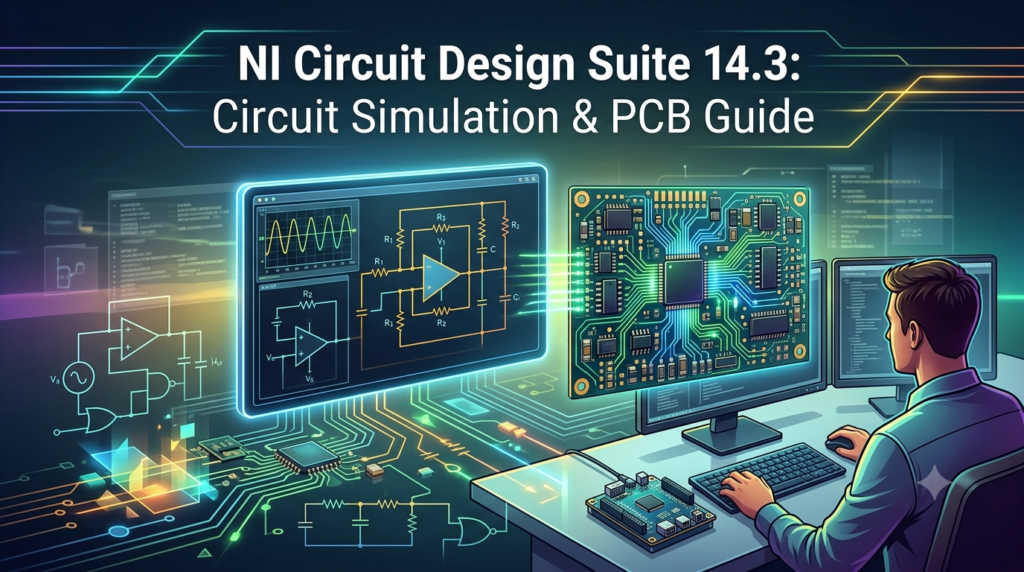
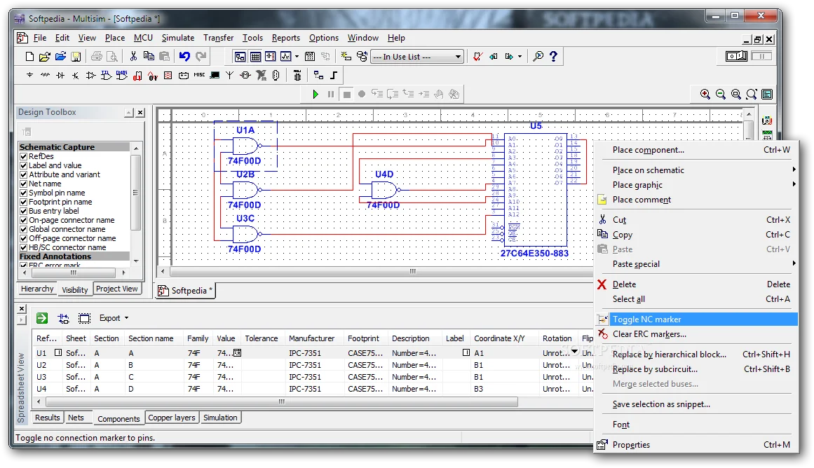
NI Circuit Design Suite 14.3 is a complete electronic design automation (EDA) solution developed by National Instruments. The suite integrates two primary applications: Multisim for schematic capture and simulation, and Ultiboard for PCB layout and routing.
The software’s core strength lies in its SPICE-based simulation engine, which enables engineers to predict circuit behavior with high accuracy before building physical prototypes . With a library of over 55,000 components validated by leading semiconductor manufacturers including Analog Devices, Infineon, NXP, and Texas Instruments, the software ensures reliable simulation results .
Circuit Design Suite serves diverse users, including researchers performing advanced circuit analysis, students learning electronics principles, and educators teaching circuit theory. The software provides an accessible platform that simplifies complex simulation tasks while maintaining professional-grade accuracy .
Key Features
Comprehensive Component Library
Circuit Design Suite 14.3 includes an extensive database of manufacturer-verified components and models. The software’s library is organized into categories like operational amplifiers, comparators, diodes, power MOSFETs, and voltage monitors . Version 14.3 added over 200 new components from manufacturers such as ROHM Semiconductor, including 27 new operational amplifiers and 14 new Schottky diodes .
Advanced SPICE Simulation
Multisim’s underlying SPICE simulation engine supports a wide range of analysis types that help users understand circuit behavior under various conditions :
-
DC Operating Point: Determines static bias conditions and verifies transistor saturation levels
-
AC Sweep: Evaluates frequency response for filters and amplifier bandwidth
-
Transient Analysis: Examines dynamic response including startup behavior and pulse response
-
Fourier Analysis: Analyzes harmonic content and distortion in circuits
-
Monte Carlo Analysis: Assesses circuit performance variation due to component tolerances
-
Parameter Sweep: Evaluates circuit response across component value ranges
-
Temperature Sweep: Simulates performance across different operating temperatures
Virtual Instruments
The software includes a suite of simulation-driven instruments that replicate real-world test equipment :
-
2-channel and 4-channel oscilloscopes
-
Function generators
-
Digital multimeters
-
Bode plotters for frequency response analysis
-
Logic analyzers and word generators
-
Spectrum analyzers
-
Network analyzers
-
Arbitrary waveform generators
Integration with Ultiboard for PCB Design
Circuit Design Suite 14.3 provides seamless integration between Multisim and Ultiboard, enabling forward and backward annotation between schematics and PCB layouts . Users can transfer designs from simulation to board layout, make changes, and synchronize updates across both environments.
Educational Features
The Education Edition of Circuit Design Suite includes enhanced features for teaching, including unlimited component limits, embedded questions, and the ability to create custom teaching materials . Both Student and Education editions provide virtual NI ELVIS instruments and support for programmable logic device (PLD) design .
What’s New in Version 14.3
Circuit Design Suite 14.3 introduced several improvements over previous versions:
-
Expanded Component Library: Over 200 new components added with simulation models and footprints from leading manufacturers
-
Enhanced Component Families: New additions across comparator, diode, operational amplifier, power MOSFET, Schottky diode, and voltage monitor categories
-
Improved Database: Updated component models from manufacturers including ROHM Semiconductor
-
Compatibility: Support for Windows 11 and Windows Server 2022 operating systems
System Requirements
Before installing Circuit Design Suite 14.3, ensure your system meets the following minimum requirements :
| Component | Minimum Requirement |
|---|---|
| Processor (32-bit) | Pentium 4M or equivalent |
| Processor (64-bit) | Pentium 4 G1 or equivalent |
| RAM | 1 GB |
| Disk Space | 2 GB |
| Screen Resolution | 1024 x 768 |
| Supported OS | Windows 11, Windows 10 IoT Enterprise 2021, Windows Server 2022 64-bit, Windows Server 2025 |
Important: National Instruments recommends disabling Windows Fast Startup during installation to prevent potential hardware detection issues .
Optional requirements include LabVIEW 2019 or later for developing custom LabVIEW-based Multisim instruments .
Installation Guide
Follow these steps to install Circuit Design Suite 14.3 on your system. The process requires an NI account and a valid license.
Step 1: Create an NI Account
Navigate to ni.com and create an account using your email address. Students with institutional email addresses can qualify for educational licensing . Confirm your email address through the verification link sent by NI.
Step 2: Download the Software
Access the Circuit Design Suite download page on the NI website. Select version 14.3 and your preferred edition (Education or Professional). The download includes NI Package Manager, which handles the installation process .
Step 3: Run the NI Package Installer
Launch the downloaded executable file. Accept the license agreements and proceed through the installation wizard. During installation, you may be prompted to disable Windows Fast Startup—follow this recommendation to avoid potential issues .
Step 4: Complete Installation
Wait for the NI Package Manager to complete the installation. This process may take several minutes. After installation completes, reboot your system.
Step 5: Activate Your License
Open the NI License Manager application. If you purchased a license or received an educational license file, select “Install License File” and browse to your .lic file to activate the software . Students may be eligible for a free 45-day trial .
How to Use Circuit Design Suite 14.3
Creating a New Design
-
Launch Multisim: Open the application from your Start menu or desktop shortcut.
-
Select Components: Use the component toolbar or search function to find and place components on the schematic workspace. The library includes over 55,000 manufacturer-verified components .
-
Wire the Circuit: Connect components using the wiring tool. Multisim features autoconnection for passive components, speeding up schematic creation .
-
Configure Simulation: Choose the appropriate simulation type for your analysis needs. Transient analysis works well for time-domain behavior, while AC sweep is ideal for frequency response evaluation .
-
Run Simulation: Execute the simulation and observe results using virtual instruments and the grapher tool.
Moving from Simulation to PCB Layout
After verifying circuit behavior through simulation, transfer the design to Ultiboard for PCB layout :
-
Select the “Transfer to Ultiboard” option to export the netlist
-
Place components and route traces in Ultiboard
-
Use forward/backward annotation to synchronize changes between schematic and layout
-
Generate industry-standard Gerber and DXF files for manufacturing
Using Virtual Instruments
Virtual instruments provide real-time visualization of circuit behavior during simulation. To use them:
-
Place instrument icons from the instrument toolbar onto your schematic
-
Connect instrument terminals to circuit nodes
-
During simulation, the instrument interface opens automatically
-
Configure measurement parameters and observe results
Best Use Cases
Academic Teaching and Student Learning
Circuit Design Suite is widely used in universities and technical institutions for electronics education. The software helps students visualize abstract circuit concepts and bridge theory with practical application . Educators can create embedded questions within circuits, allowing students to test their understanding as they work through designs .
Rapid Prototyping and Design Verification
Engineers use the software to verify circuit performance before committing to physical prototypes. By simulating designs and analyzing results, teams can identify potential issues early in the development cycle, saving significant time and cost . The integration with Ultiboard enables a smooth transition from simulation to PCB layout.
Research and Advanced Circuit Analysis
Researchers leverage Multisim’s comprehensive analysis tools to investigate circuit behavior across operating conditions. Features like Monte Carlo, parameter sweeps, and noise analysis help characterize designs for reliability and performance optimization .
Power Electronics Design
Circuit Design Suite supports power electronics applications, including switch-mode power supply design. The software’s component library includes relevant models, and analysis tools can evaluate efficiency, stability, and switching behavior .
Advantages and Limitations
Advantages
-
Comprehensive Simulation Capabilities: Wide range of analysis types supports diverse design verification needs
-
Seamless PCB Integration: Smooth workflow between schematic design, simulation, and PCB layout
-
Extensive Component Library: Over 55,000 validated components reduce manual model creation
-
Educational Value: Features like embedded questions and virtual instruments support effective teaching
-
Virtual Instruments: Simulation-driven test equipment reduces need for physical lab setups
Limitations
-
System Requirements: Full functionality requires modern Windows systems with adequate resources
-
Version-Specific Compatibility: Some advanced features vary between Student, Education, and Professional editions
-
Licensing: Commercial use requires paid licenses, though educational options are available
Alternatives to Circuit Design Suite
LTspice
LTspice is a free SPICE simulator offering excellent analog simulation capabilities. It is widely used for power electronics and analog circuit design. Unlike Circuit Design Suite, LTspice does not include integrated PCB layout tools.
Altium Designer
Altium Designer is a comprehensive PCB design platform with robust schematic capture and layout capabilities. It offers professional-grade features but typically requires higher investment and has a steeper learning curve than Circuit Design Suite.
KiCad
KiCad is an open-source EDA suite offering schematic capture, PCB layout, and simulation. It provides a cost-effective alternative for hobbyists and small projects, though its simulation capabilities are less integrated than Circuit Design Suite’s.
Cadence PSpice
PSpice is a professional-grade SPICE simulation tool with advanced modeling and analysis features. It is commonly used in semiconductor and high-reliability design environments but may require additional modules for PCB integration.
Frequently Asked Questions
What is NI Circuit Design Suite used for?
NI Circuit Design Suite combines Multisim for circuit simulation and Ultiboard for PCB layout. It is used by engineers, educators, and students to design, simulate, and prototype electronic circuits. The software helps verify circuit behavior before physical prototyping and supports teaching of electronics principles .
What is the difference between Multisim and Circuit Design Suite?
Circuit Design Suite is the complete software package that includes Multisim, Ultiboard, and additional tools. Multisim is the schematic capture and simulation component within the suite, while Ultiboard handles PCB layout and routing .
How many components are in the Multisim library?
Multisim includes a library of over 55,000 manufacturer-verified components validated by leading semiconductor manufacturers like Analog Devices, Infineon, and Texas Instruments . The Education Edition includes approximately 14,697 components, while the Student Edition includes 5,255 .
Can students use Circuit Design Suite for free?
Many educational institutions provide access to Circuit Design Suite for students. National Instruments offers a free 45-day trial for students, and educational licenses are available through institutions and authorized resellers like Studica . Students should check with their institution for available licenses.
What analysis types does Multisim support?
Multisim supports DC operating point, AC sweep, transient analysis, Fourier analysis, Monte Carlo analysis, parameter sweep, temperature sweep, distortion analysis, noise analysis, pole-zero analysis, sensitivity analysis, and transfer function analysis .
What is the latest version of Circuit Design Suite?
Circuit Design Suite 14.3 is the latest version at the time of this writing, with release dates spanning 2022 through 2025 . Users should check the NI website for current version information and updates.
How do I transition from Multisim simulation to PCB design?
Multisim integrates with Ultiboard to provide a seamless transition from simulation to PCB layout. Use the “Transfer to Ultiboard” option to export your schematic netlist. You can then place components, route traces, and generate manufacturing files. Forward and backward annotation keeps schematic and layout synchronized .
What are the system requirements for Circuit Design Suite 14.3?
The software requires a Pentium 4M or equivalent processor, 1 GB RAM, 2 GB disk space, 1024 x 768 screen resolution, and Windows 11 or Windows Server 2022. NI recommends disabling Windows Fast Startup during installation .
Final Thoughts
NI Circuit Design Suite 14.3 provides a comprehensive environment for circuit design, simulation, and PCB layout. Its combination of SPICE simulation capabilities, extensive component library, and seamless integration with Ultiboard makes it a valuable tool for both educational and professional applications.
The software’s focus on verification before prototyping helps engineers identify design issues early, reducing costly iterations. For students and educators, the suite offers hands-on learning opportunities that bridge theoretical concepts with practical application.
When evaluating Circuit Design Suite for your needs, consider your specific requirements for simulation types, component library access, and PCB layout capabilities. The Education Edition provides additional features for teaching, while Professional editions offer full access to the complete component library and analysis tools.
Staying informed about security updates is also essential. Vulnerabilities have been identified in Circuit Design Suite versions up to 14.3.0 . Ensure you install the latest patches and updates available through National Instruments to maintain security and performance.
Our Paid Service
“We do not sell or provide any software. We only offer professional support services. If any software on your system is not working properly, or you are facing installation errors, crashes, or any other technical issue — just contact us. We will help you fix the problem quickly and remotely via AnyDesk. No software will be provided from our side — only expert troubleshooting and support.”